EKRA
Вход
Products
  • Relay Protection & Automation
  • Control & Automation Systems
  • Medium-Voltage Drive
  • Low-Voltage Equipment & Systems

Products

Solutions
Services
  • R&D
  • Simulations and Calculations
  • Design Works
  • Adjustment Works
  • Training

Services

Company
  • About EKRA
  • EKRA Group
  • Mission & Values
  • References
  • History
  • Sustainability
  • Press Center

Company

    Support Contacts
    EKRA
    Products
    • Relay Protection & Automation
    • Control & Automation Systems
    • Medium-Voltage Drive
    • Low-Voltage Equipment & Systems

    Products

    Solutions
    Services
    • R&D
    • Simulations and Calculations
    • Design Works
    • Adjustment Works
    • Training

    Services

    Company
    • About EKRA
    • EKRA Group
    • Mission & Values
    • References
    • History
    • Sustainability
    • Press Center

    Company

      Support Contacts
      EKRA
      EKRA
      • Products
        • Back
        • Products
        • Relay Protection & Automation
        • Control & Automation Systems
        • Medium-Voltage Drive
        • Low-Voltage Equipment & Systems
      • Solutions
      • Services
        • Back
        • Services
        • R&D
        • Simulations and Calculations
        • Design Works
        • Adjustment Works
        • Training
      • Company
        • Back
        • Company
        • About EKRA
        • EKRA Group
        • Mission & Values
        • References
        • History
        • Sustainability
        • Press Center
      • Support
      • Contacts
      • Products
      • Relay Protection & Automation
      • Transmission 66-765 kV

      Bay Controller
      ED2-BC

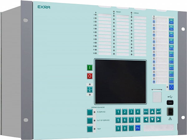
      Bay Controller ED2-BC
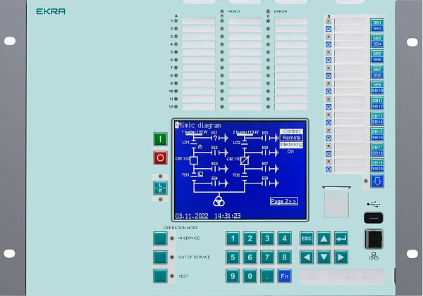
      Front panel
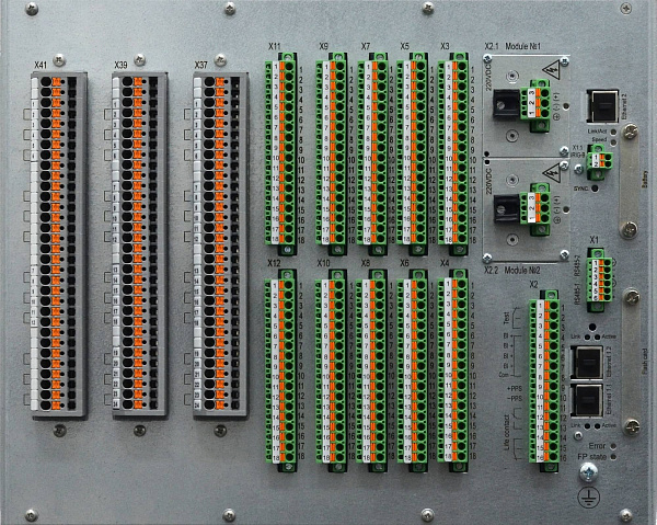
      Rear view
      Bay Controller ED2-BC
      Front panel
      Rear view

      The ED2-BC designed for controlling and monitoring bays.

      Structurally, the IED is made as a set of units combined into a cassette. When it is necessary to increase the number of signals, an expansion cassette can be connected to IEDs.

      Front panel

      Large graphic display is designed to show the mimic diagram as well as the information necessary for the user

      On/Off electronic switches used to enable/disable relay protection and automation functionalities directly from the device front panel

      Two-color LEDs (green/red) are provided with status latching or non-latching

      The following buttons are provided on the IED front panel:

      • IED control buttons
      • circuit-breaker control functional buttons
      • keyboard

      Ethernet for PC connection, USB for Flash drive connection

      Rear view

      IED is powered from sources of 110 VDC, 220 VDC

      Maximum total amount of analog inputs is 48

      Up to 256 freely configurable binary inputs/outputs

      IED has 2 RS485 ports and up to 3 Ethernet ports supporting protocols IEC 60850-103/104, Modbus RTU/TCP, GOOSE, MMS (IEC 61850). For IEDs supporting IEC 61850, RJ45 or duplex LC Ethernet ports are provided featuring PRP hardware redundancy capability

      IED supports multiple types of hardware synchronization:

      1. PPS:
        • Differential communication line (twisted pair, using optional converter)
        • Fiber-optic line (using optional converter)
        • 24 V synchronization pulse
      2. IRIG-B:
        • Differential communication line (twisted pair)
        • Fiber-optic line (using optional converter)

      Designed for their quick replacement with no need to dismantle the IED
      Display Electronic switches Two-color LEDs Functional control IED interfaces Hot swap power supply (optional) Analog inputs Binary inputs/outputs Communication interfaces Communication interfaces Communication interfaces Hardware synchronization Hardware synchronization Compartments offering access to the IED’s memory card and lithium battery
      • Functions
      • Features
      • Specifications

      ED2-BC protection function ANSI code
      Phase Discontinuity Protection 46BC
      Tripping logic 94
      Trip circuit supervision 74TC
      Breaker failure protection 50BF
      Synchrocheck, energizing check and synchronizing 25
      Autorecloser (3 Phase, 1 Phase) 79
      Lockout 86
      Fuse Failure / VT Supervision 60
      Circuit breaker control / Supervision 52
      CT Supervision
      Open-phase protection
      Switchgear interlocking
      Three-phase Measurement
      One-phase Measurement
      Disturbance recorder
      Event recorder
      Self-test function

      Multitasking
      Structurally, the IED is made as a set of units combined into a cassette. The IED platform with its modular architecture of hardware units enables device adapting to any primary facility layout. All binary inputs, relays, LEDs, switch buttons can be freely assigned
      IED operation in extended frequency range
      Depending on configuration, the device is able to operate within frequency range from 3 to 95 Hz
      Application
      Circuit-breaker control automation receives closing and opening commands, offers control and latching of circuit-breaker position, protection against multiple actuation
      Disconnectors interlocking
      Interlocking logics for up to 10 switching devices for various primary diagrams can be implemented

      Specification Value
      Rated alternating current, A 1 or 5 (selected via software)
      Rated frequency, Hz 50
      Rated AC voltage, V 100
      Rated auxiliary DC voltage, V 220 / 110
      Operational voltage range -20 % … +20 %
      Interruption, ms 120
      Recommended temperature for continuous operation (according to IEC 60255-1), °C -10 … +55
      Permissible temporary operation temperature, °C -25 … +60
      Long-term storage and transportation temperature, °C -40 … +70
      Altitude, m up to 2,000
      Upper humidity value, % 80
      Ingress protection (IP) degree IP52 — front panel
      IP20 — rear panel
      Permissible overload of current inputs, continuous 5 * Ir
      Permissible overload of current inputs, 1s 100 * Ir
      Burden at Ir, VA <0.5
      Permissible overload of voltage inputs, continuous 3 * Ur
      Burden at Ur, VA <0.1
      Maximum switching voltage, V 250
      Continuous current, А 8
      Switching capacity of contacts (making current) up to 30 А for 0.20 s
      Maximum operation time, ms 10
      Newsletter subscription
      • Products
        • Relay Protection & Automation
        • Control & Automation Systems
        • Medium-Voltage Drive
        • Low-Voltage Equipment & Systems
      • Services
        • R&D
        • Simulations and Calculations
        • Design Works
        • Adjustment Works
        • Training
      • Company
        • About EKRA
        • EKRA Group
        • Mission & Values
        • References
        • History
        • Sustainability
        • Press Center
      • Support
        • Technical Support
        • Support Offices
        • Video Tutorials
      Contacts
      +7 (8352) 220-110
      +7 (8352) 220-130
      ekra@ekra.ru
      3 Yakovlev prospect, Cheboksary,
      Chuvashia — Chuvash Republic,
      428020, Russia
      2007-2023 © EKRA Research & Production Enterprise Ltd. All rights reserved
      Privacy Policy
      The website ekra.ru uses cookies. By continuing to use this site, you agree to allow us to use cookies in your browser with a view to improving user experience. If desired, you may disable the storage of cookies in your browser settings.